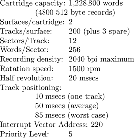
The RK disk storage system employs a removable disk cartridge containing a single disk, which is mounted inside a drive with moving read/write heads.
The device designated RK11-D consists of a disk controller together with a single drive. Additional drives, designated RK05, up to a total of seven, may be added to a single RK11-D.
A requirement for more than eight drives would require an additional controller with a different set of UNIBUS addresses. Also the code in the file “rk.c” would have to be modified to handle the case of two or more controllers. This case is most unlikely because requirements for large amounts of on-line disk storage will be more economically provided otherwise e.g. by the RP04 disk system.
Unibus Register Addresses |
||
Drive Status |
RKDS |
777400 |
Error |
RKER |
777402 |
Control Status |
RKCS |
777404 |
Word Count |
RKWC |
777406 |
Current bus address |
RKBA |
777410 |
Disk address |
RKDA |
777412 |
Data Buffer |
RKDB |
777416 |
The average total access time is 70 milllseconds. With multi-drive subsystems, seeking by one drive may be overlapped with reading or writing by another drive. However this feature is not used by UNIX because of bugs which existed at one time in the hardware controller.
In initiating a data transfer, RKDA, RRBA and RKC are set, and then RKCS is set. Upon completion, status information is available in RKCS, RRER and RKDS. When an error occurs, UNIX simply calls “deverror” (2447) to display RKER and RKDS on the system console, without any attempt at analysis. An operation is repeated up to ten times before an error is reported by the device driver.
The register formats which are described fully in the “PDP11 Peripherals Handbook” are reflected in the program code at several points. The following summaries suffice to describe the features used by UNIX:
Control Status Register (RKCS) |
|
bit |
description |
15 |
Set when any bit of RKER (the |
Error Register) is set; |
|
7 |
Set when the control is no |
longer engaged in actively |
|
executing a function and is ready |
|
to accept a command; |
|
6 |
When set, the control will issue |
an interrupt to vector address |
|
220 upon operation completion or |
|
error; |
|
5–4 |
Memory Extension. The two most |
significant bits of the 13 bit |
|
physical bus address. (The other |
|
16 bits are recorded in RKBA.); |
|
3–1 |
Function to be performed: |
CONTROL RESET: 000 |
|
WRITE: 001 |
|
READ: 010 |
|
etc., |
|
0 |
Initiate the function designated |
by bits 1 to 3 when set. (write |
|
only); |
|
Word Count Register (RKWC) |
|
Contains the twos complement of the number of words to be transferred.
Disk Address Register (RKDA) |
|
bit |
description |
15–13 |
Drive number (0 to 7) |
12–5 |
Cylinder number (0 to 199) |
4 |
Surface number (0,1) |
3-0 |
Sector address (0 to 11) |